The IRISS Ecosystem for Safety, Reliability & Sustainability
The reliability of electrical power creation and distribution must be continually safeguarded and improved. This does not happen by chance or through reactionary-maintenance tasks, and it must be focused on from the early design stages and continue through the life of the assets tasked with these functions. Using the IRISS Ecosystem to adopt a “Monitor, Inspect, & Manage” program is the proactive way to maximizing the value and cost of both your workforce and assets.
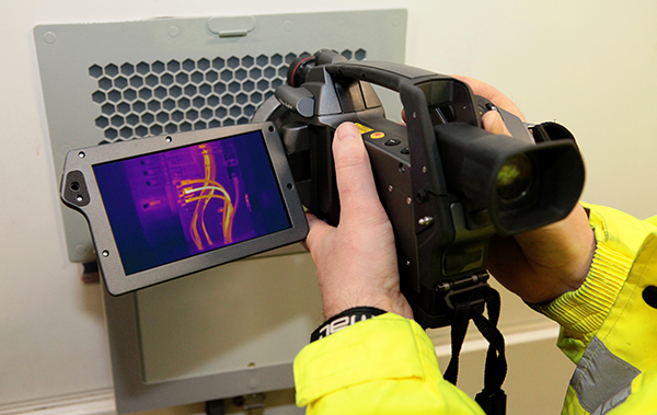
Infrared Inspection Solutions
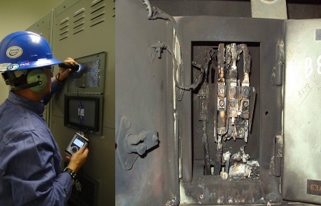
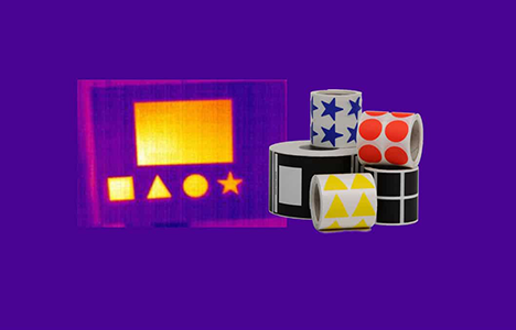
Infrared inspection Solutions such as IRISS’s infrared windows and handheld cameras are essential for safety and reliability.
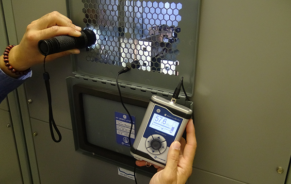
Ultrasound Inspection Solutions
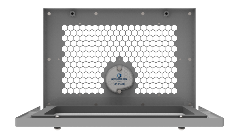
Ultrasound inspection using sound ports and handheld testing devices plays a critical role when used in asset inspection and management programs.
Safe-Connect Thermochromic Solutions
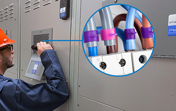
The Safe-Connect product line from IRISS offers the advantage of thermochromic science for visual indication of asset health providing 24/7 safety monitoring to give a predictive warning on overheated equipment.

Asset Management Solutions
E Sentry is a comprehensive cloud-based asset management system designed to streamline and optimize the operations of maintenance and reliability teams.
CAP Series
Unveil the Power of Precision with the IRISS CAP Series! The CAP-B is tailored for the power generation sector, offering a large-format window for infrared, visual, and UV inspections on non-segmented bus bars.
VP Series
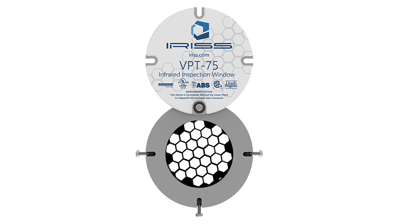
Elevate Your Asset Monitoring to the Next Level! The VPDS Ultrasound Sensor offers the safest and most effective ultrasound inspection for energized electrical assets, featuring an in-panel transducer.
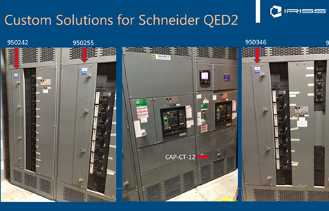
FlexIR Custom Solutions
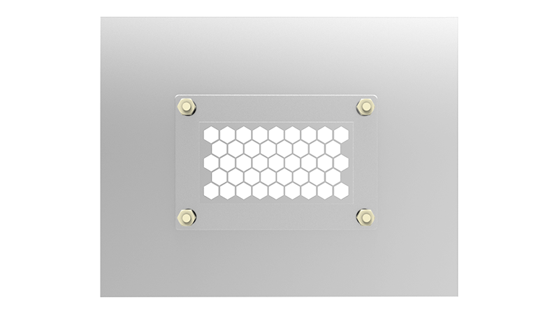
Where Safety and Reliability Meet Customization in Asset Management. Traditional window designs often fall short in accommodating various equipment types, especially when panel space is limited.
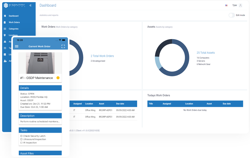
E Sentry Systems
Implementing the E Sentry intelligent asset management system allows you to record all historical data from inspections and upload to the cloud for reference in condition trending, providing the oversight to predict when assets may require maintenance.
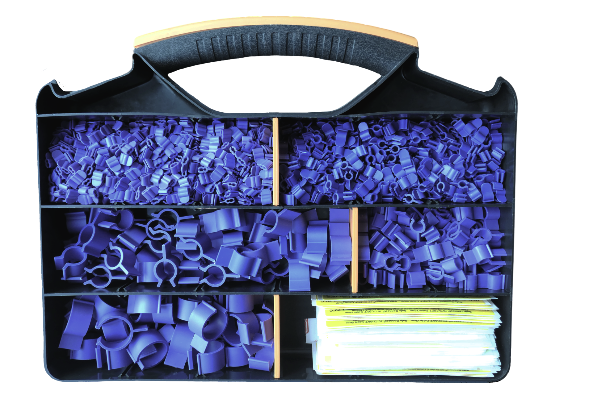
Safe-Connect Thermochromic Solutions
Your comprehensive solution for electrical asset management that prioritizes safety and precision. Our ThermoClips feature patented thermochromic technology, offering overtemperature indicators.
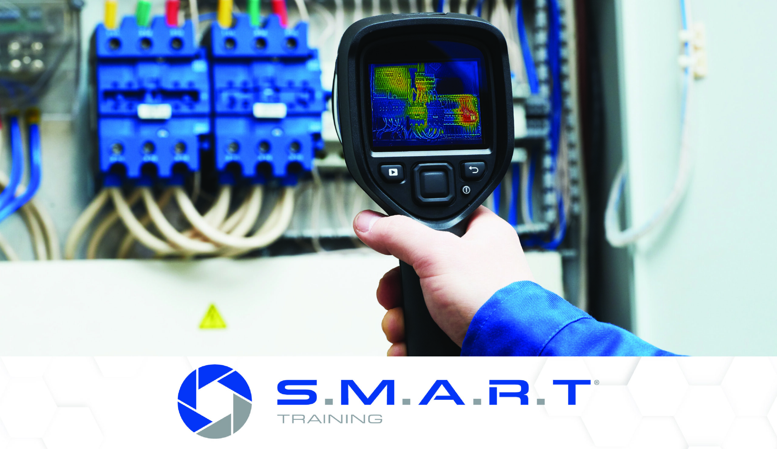
SMART Training
The Safety and Maintenance Academy of Reliability Technologies® offers online training and certifications that provide you with the knowledge and practical experience necessary to complete electrical inspections safely and efficiently.