August 15, 2015
Know Your Emissivity
What is Emissivity? The material emissivity (written as “?” or “e”) is the relative power of its surface to emit heat by radiation. Materials are assigned an emissivity value between 0 and 1.0. Emissivity is a measure of a material’s ability to emit infrared energy. The emissivity of a surface is the ratio of the […]
What is Emissivity?
The material emissivity (written as “?” or “e”) is the relative power of its surface to emit heat by radiation. Materials are assigned an emissivity value between 0 and 1.0. Emissivity is a measure of a material’s ability to emit infrared energy. The emissivity of a surface is the ratio of the energy radiated from it to that from a blackbody at the same temperature, the same wavelength and under the same viewing conditions.
The Importance of Emissivity in Electrical Thermography
Manufacturing facilities are full of equipment requiring periodic infrared (IR) inspection. The goal is to obtain an accurate assessment of equipment health. The most critical part of the assessment is properly compensating for the various emissivity values of all the components measured. Slight errors in emissivity compensation can lead to significant errors in temperature and ?T (difference in temperature) calculations. Electrical cabinets are a good example, as they may contain materials with emissivity values ranging from 0.07 to 0.95.
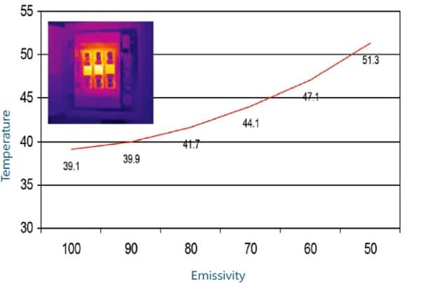
The graph shows how calculated temperatures can be adversely affected when the imager’s emissivity value is set too high. In this example, the emissivity of the target is 0.50; the graph shows the apparent temperature when the imager’s emissivity setting is stepped down from 1.0 to 0.50. When emissivity is properly compensated for, the actual temperature is shown to be 12.2° higher.
Magnitude of Error
One of the most misunderstood concepts in thermography is the degree to which errors in emissivity settings (and errors in window transmissivity compensation) will affect temperature and ?T (difference in temperature) accuracy. As demonstrated by the Stefan-Boltzmann Law, the radiated infrared energy emitted by a target surface is exponentially related to the absolute temperature of that surface.
Therefore, as the temperature increases, radiant energy increases proportionally by the absolute temperature to the 4th power. Incorrect camera settings such as emissivity and infrared window transmission rates will result in incorrect temperature values. Furthermore, because the relationship is exponential, this error will worsen as the component increases in temperature. Consider the effect on ?T comparisons, which are by their nature a comparison between different temperatures. The resulting calculations are apt to be radically understated, which could easily lead thermographers to misdiagnose the severity of a fault.
Emissivity Measurement
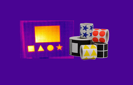
For some components, it can be difficult to determine the correct emissivity value. In the case of a highly polished component like a bus bar, the actual emissivity may be so low as to make temperature measurement impractical. It is strongly recommended that thermographers understand the surface of the primary targets. Once identified, those surfaces should be treated with a high-emissivity covering so that all targets have a standardized emissivity.
Thermographers can apply electrical tape, high-temperature paint (such as grill paint), or high-emissivity labels. When all targets have a standard emissivity, refection issues are minimized and measurement errors from reflected ambient energy are greatly reduced. High-emissivity targets of varying shapes can also provide a useful point-of-reference both for the thermographer and the technician making repairs.